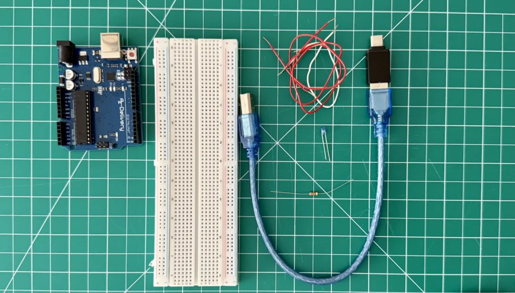
In this beginner Arduino project, I build and program a simple external LED circuit using an Arduino UNO.
The goal of this tutorial is to explain the complete process from the beginning. I start by preparing the Arduino IDE, connecting the Arduino UNO to the computer, and checking that the board is communicating correctly.
After that, I built a basic LED circuit on a breadboard and uploaded a simple Blink program to the Arduino. The program repeatedly switches the LED on and off, creating a blinking effect.
This is a great first project for anyone completely new to Arduino because it introduces both sides of an electronics project: building the physical circuit and writing the code that controls it.
Tools & materials
Tools
- Computer
Materials
- Arduino UNO
- Breadboard
- LED
- Resistor
- Jumper wires
- USB cable
Software
- Arduino IDE
Step by step
Build process
Install and prepare the Arduino IDE
Start by downloading and installing the Arduino IDE on your computer.
The Arduino IDE is the software used to write code and upload it to the Arduino board. Once it is installed, open the application and connect the Arduino UNO to your computer using a USB cable.
Inside the Arduino IDE, select Arduino UNO as the board. You will also need to select the communication port connected to the Arduino.
Choosing the correct board and port is important because the computer needs to know which device should receive the program.
If the program does not upload, check the selected board, port, USB cable, and connection before changing the circuit.
Prepare the LED circuit
Place the LED on the breadboard, making sure that each leg is inserted into a different row. An LED has polarity, which means it must be connected in the correct direction.
The longer leg is normally the positive side, known as the anode. The shorter leg is the negative side, known as the cathode.
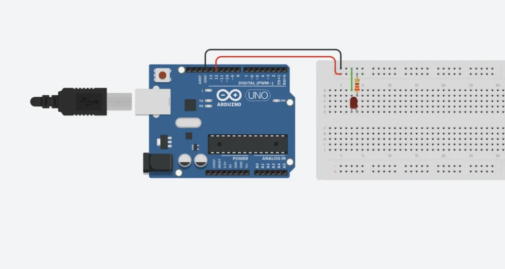
Connect the positive side of the LED to one of the Arduino UNO’s digital output pins through a resistor.
Connect the negative side of the LED to one of the Arduino UNO’s GND pins.
The resistor is an important part of the circuit because it limits the amount of current passing through the LED and helps prevent damage.
Follow the wiring shown in the video carefully, especially when selecting the digital pin and positioning the components on the breadboard.
Write the Blink program
Once the circuit is ready, create the Blink program inside the Arduino IDE.
First, configure the Arduino pin connected to the LED as an output. The program can then change the state of that pin between HIGH and LOW.
When the pin is HIGH, the LED turns on.
When the pin is LOW, the LED turns off.
A delay is added after each change so that the LED remains on and off long enough for the blinking effect to be visible.
Make sure the PIN number used in the program matches the physical pin connected to the LED.
Upload the program
Before uploading the program, check the circuit one more time.
Make sure the LED is facing the correct direction, the resistor is connected properly, and the jumper wires are inserted into the correct breadboard rows.
Click the upload button in the Arduino IDE and wait for the program to compile and transfer to the Arduino UNO.
Once the upload is complete, the LED should begin blinking automatically.
If the LED does not turn on, check its orientation, confirm that the correct digital pin is being used, and inspect every breadboard connection.
Experiment with the blinking speed
After the circuit is working, try changing the delay values inside the program.
A smaller delay value will make the LED blink faster. A larger delay value will keep the LED on and off for longer.
This simple experiment is a useful way to understand how changes in the code affect a physical electronic component.
You can also connect the LED to another digital pin on the Arduino UNO. Remember to update the pin number in the program before uploading it again.
Code Example for Arduino Blinking an LED
In the following, you can see a simple example of how you can program your Arduino UNO in order to blink an LED.
int ledPin = 13; // Match this to your physical pin

void setup() {
  pinMode(ledPin, OUTPUT); // Configure pin as output
}

void loop() {
  digitalWrite(ledPin, HIGH);   // Turn LED on
  delay(1000);                  // Wait for 1 second
  digitalWrite(ledPin, LOW);    // Turn LED off
  delay(1000);                  // Wait for 1 second
}
Circuit diagram
And finally, here you can see a clear circuit diagram, so you can wire up your project in a clearer way!
Final result
The final result is a working LED circuit controlled by an Arduino UNO.
After uploading the program, the LED repeatedly turns on and off according to the timing written in the code. By changing the delay values, it is also possible to control how quickly the LED blinks.
Although this is a small project, it is an important first step into Arduino and electronics. It combines a physical circuit with a simple program and demonstrates how code can control an electronic component in the real world.
The same principles used in this project can later be applied to buttons, sensors, motors, displays, lighting projects, and more advanced Arduino builds.