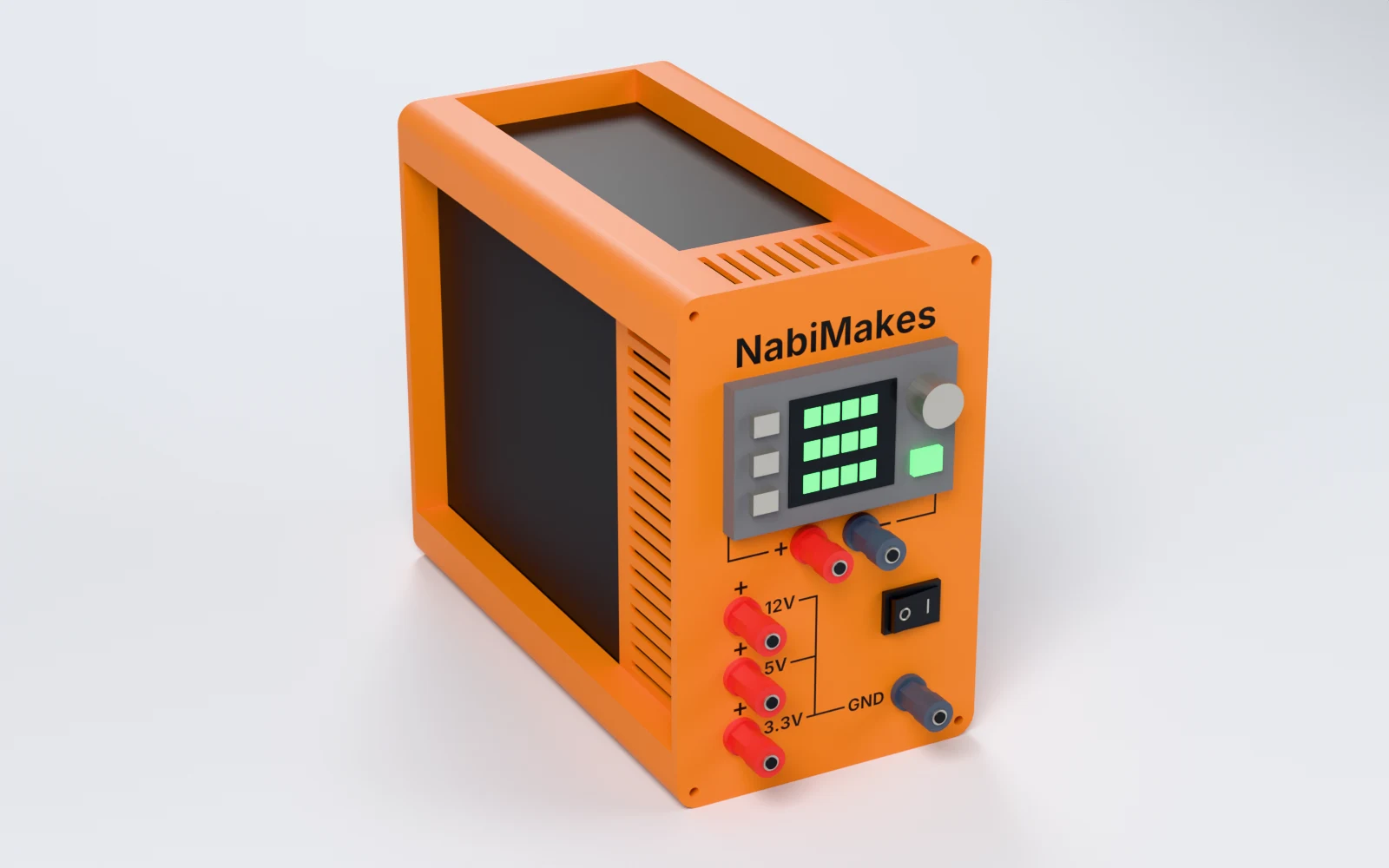
What can you build with PSU Enclosure Studio?
Any ATX, SFX or SFX-L power supply, or one you measure, from 60–250 mm wide. Makers build:
- A bench supply with fixed 12 V, 5 V and 3.3 V outputs on binding posts.
- A variable supply around an XY-SK120 or DPS module, with its own posts and fuse.
- A USB charging station with a switch and an LED on the front.
- A small SFX supply for a crowded bench, lying flat with a wide front.
- A front panel alone, printed as a drilling template for a case of your own.
How do you design the enclosure, step by step?
Five steps take you from the power supply to the pieces to print. The enclosure beside them follows every change, assembled or laid out for printing.
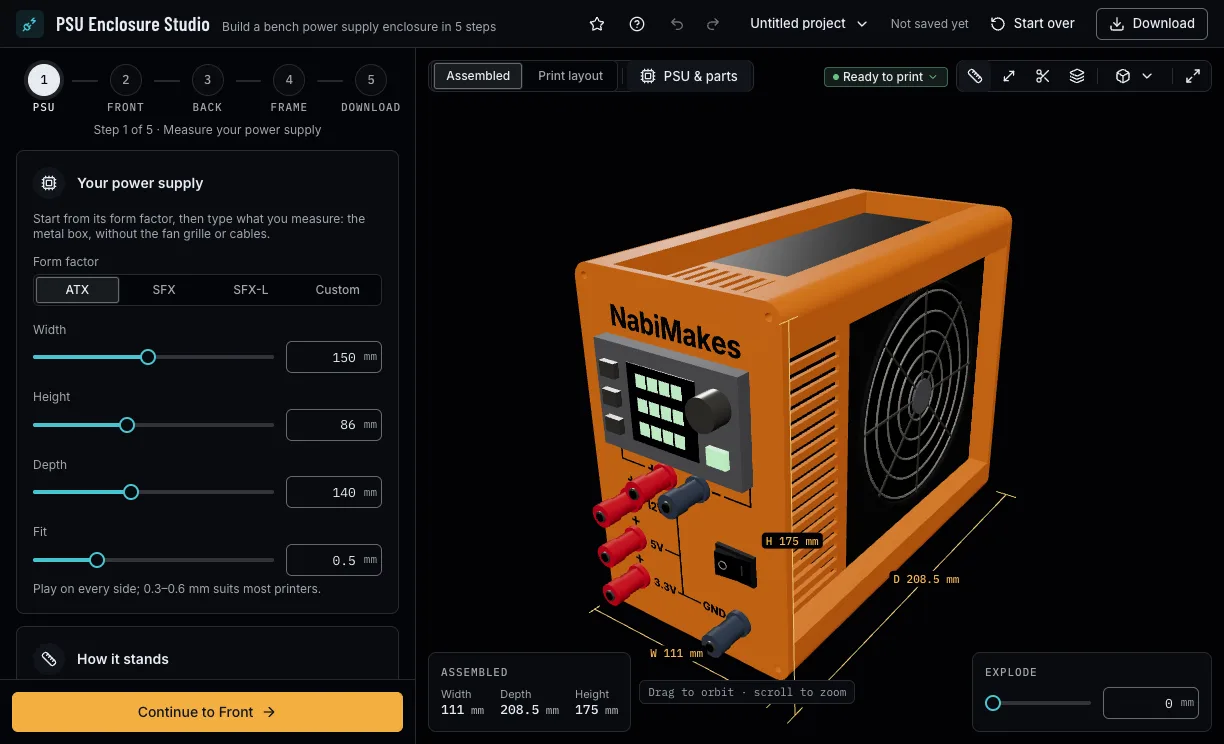
1. Measure your power supply
Pick ATX, SFX or SFX-L, or Custom and type the size you measured, lying flat. Set the fit around it, whether it stands upright (a tall front) or lies flat (a wide front), and its screw pattern, so the back bezel lines up with its screw holes.
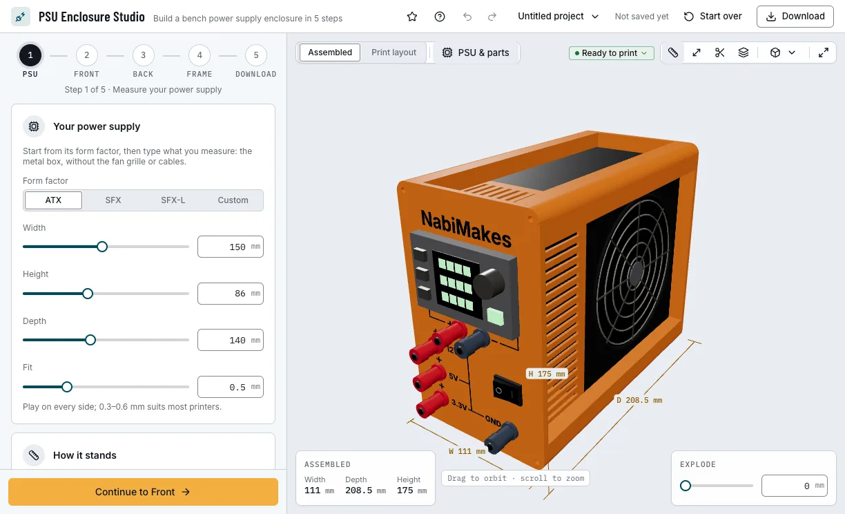
Step 1: the power supply the case is built around. 2. Lay out the front panel
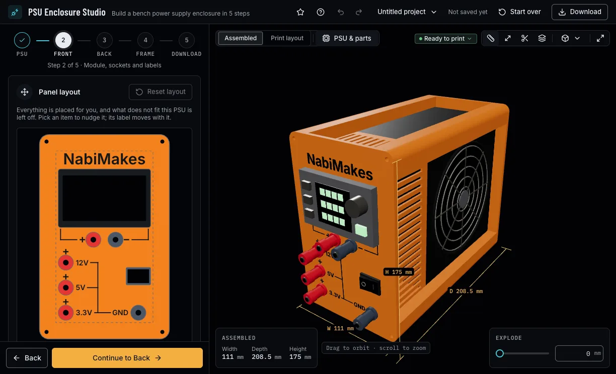
Choose a variable module or none, the rails and their labels, the ground, fuses, binding posts and components such as USB chargers, switches and LEDs. The tool places them in columns and shows the panel flat; drag the panel preview to nudge an item, and it tells you what does not fit.
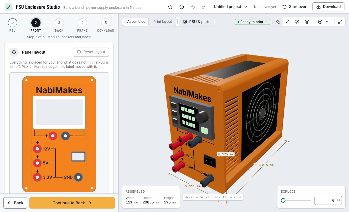
Step 2: the module, the outputs and the labels. 3. Shape the back bezel
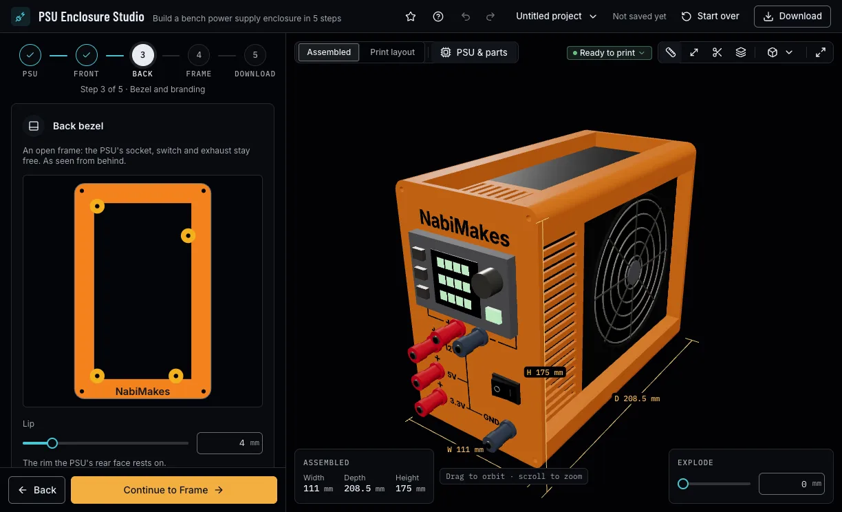
The back bezel frames the power supply's own back, so its switch, socket and fan stay open. Set the lip that holds it and the brand engraved in its border.
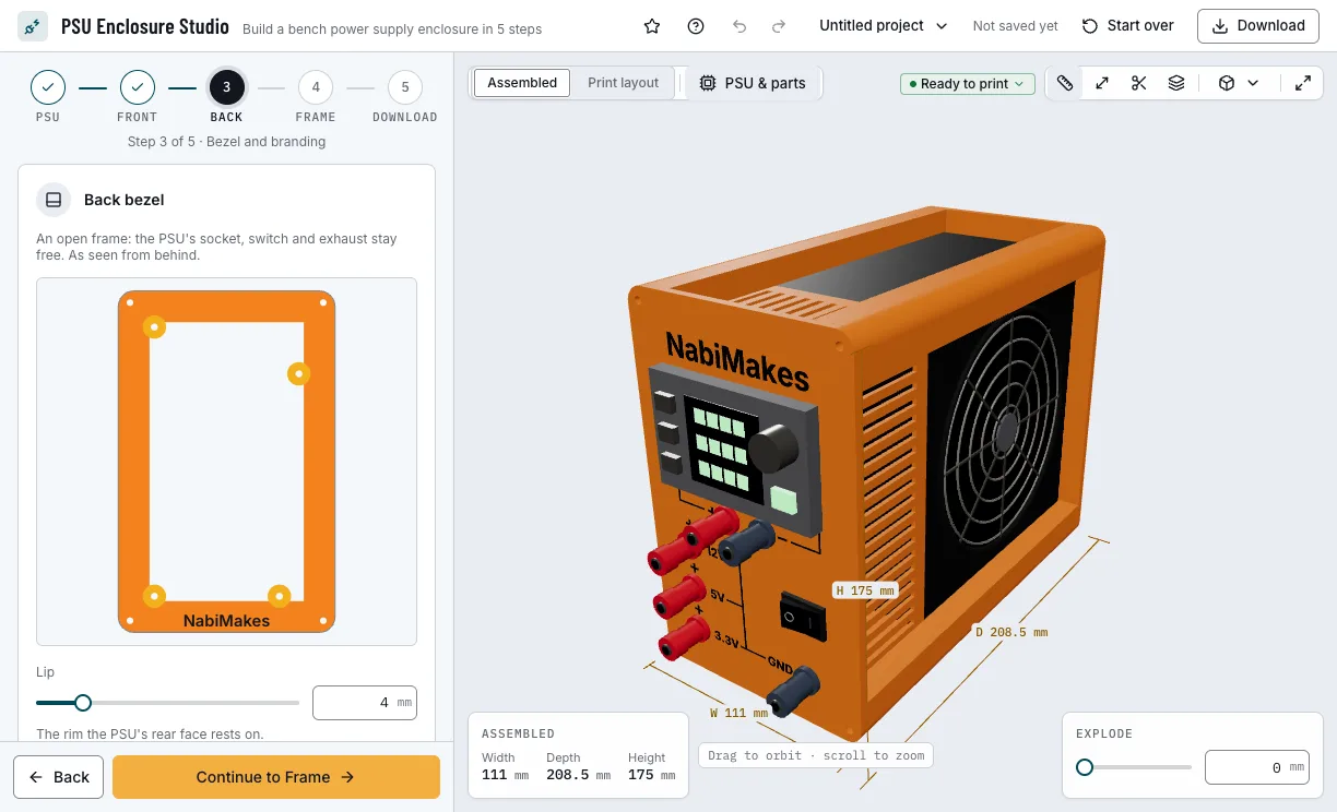
Step 3: the bezel around the PSU's back. 4. Choose how the frame joins
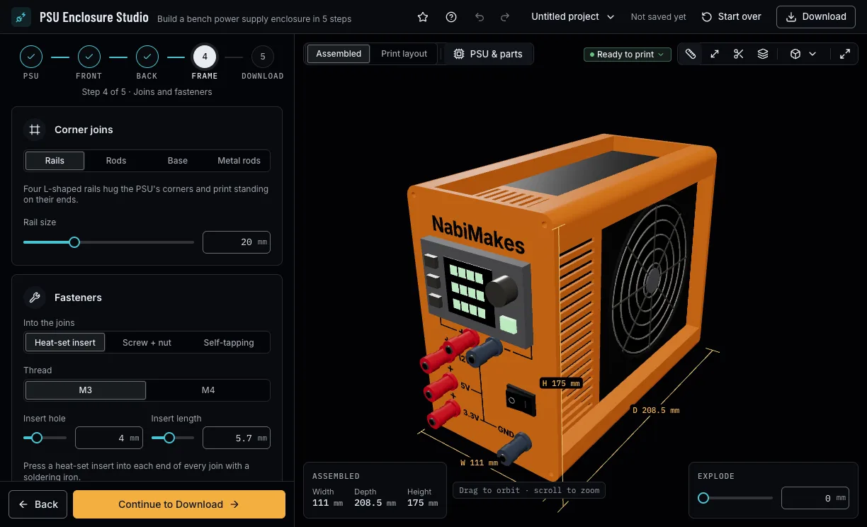
Rails at the corners, printed rods, metal rods or a base hold the two panels apart; a sleeve can close the wiring space. Pick heat-set inserts, screws and nuts or self-tapping screws, the panels' thickness and how deep the wiring space is, or let Fit to components size it.
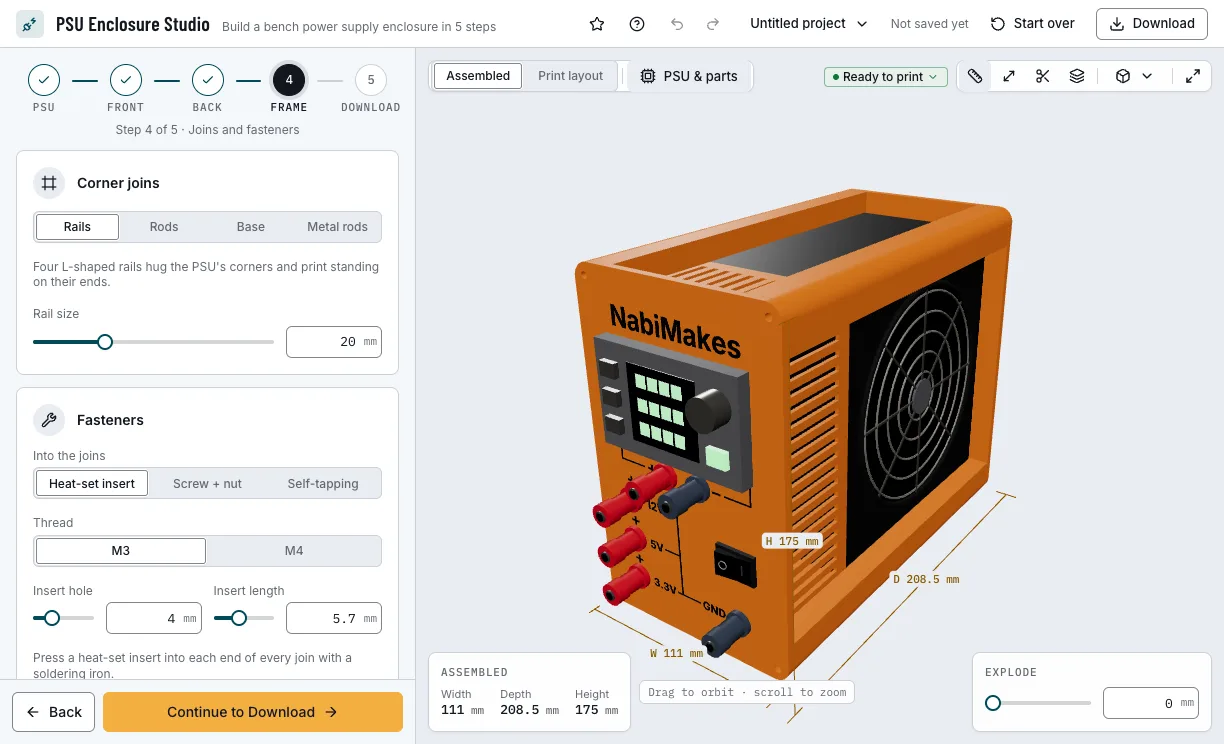
Step 4: what holds the panels together. 5. Pick the pieces and download
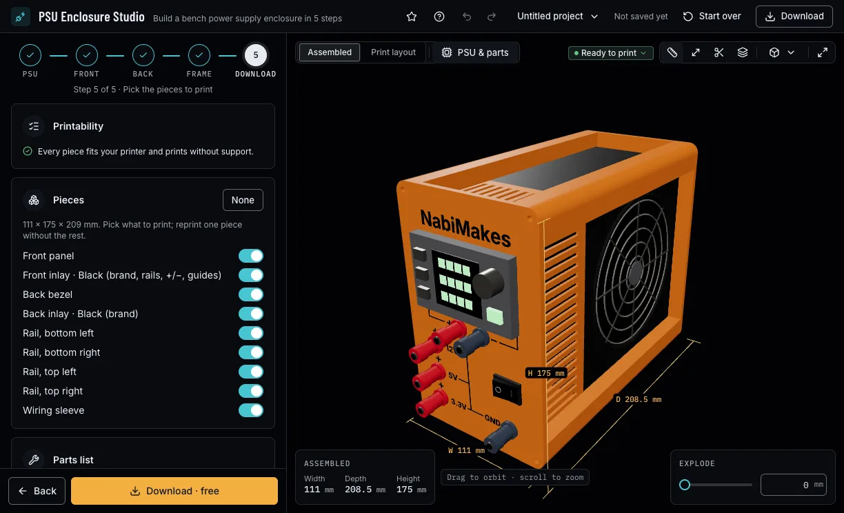
Choose the pieces to print, 3MF or STL, and one file or one per piece. The parts list counts the screws with their lengths, the inserts or nuts, the posts, fuse holders and components to buy. Downloads need a free NabiMakes account.
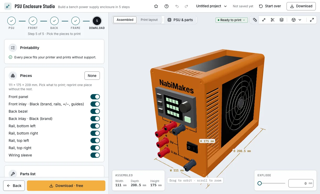
Step 5: the pieces and the parts list.
Which enclosures can you start from?
Each example opens in PSU Enclosure Studio as a new design, beside your own.
ATX bench supply
An upright ATX supply with an XY-SK120 module, three fixed rails and a switch.
- ATX
- XY-SK120
- 12 · 5 · 3.3 V
- Free
Fixed rails only
No module: the three rails on binding posts, the 12 V rail fused.
- ATX
- No module
- Fused 12 V
- Free
SFX lying flat
A small SFX supply with a wide, low front: 12 V and 5 V and a switch, standing on a base.
- SFX 125 × 63.5
- Flat
- 12 · 5 V
- Base
- Free
Rods, no inserts
Round printed rods at the corners, held by self-tapping screws: nothing to melt in.
- ATX 150 × 86
- Rods
- Self-tapping
- Free
Which print settings work best for the enclosure?
Every piece prints as it lies in the file, without supports: the panels flat (face up with the marks on top, unless something on their inside needs the bed), the joins standing up. The layer height is a starting point for your slicer; the thinnest wall is the one the printer checks hold each filament to. With inlays, a printer with several filaments prints the marks in their own colour.
| Filament | Layer height to start | Thinnest wall | Supports | Notes |
|---|---|---|---|---|
| PLA | 0.2 mm | 0.8 mm | None | Fine for the panels; keep the supply's vents clear, PLA softens near hot parts. |
| PETG | 0.2 mm | 0.8 mm | None | The better choice near the supply's heat; tougher joins and corners. |
Tips for an enclosure that goes together well
- Measure the power supply with calipers, lying flat, and keep the fit at 0.5 mm or more: printed walls are never quite straight.
- Print the front panel first: it is quick, and you can try the module, posts and switches in it before the rest.
- Let Fit to components set the wiring depth, so the deepest part behind the panel has room.
- Keep each pair of binding posts at least 16 mm apart, so banana plugs and spade terminals fit side by side.
- Before you print, check it on the view's bar: Dimensions shows its size, Measure the distance between two points, Section cuts it open and Layers steps through it as your printer will.
What if the module will not clip in, or a part is left off?
- The variable module will not clip into the panel
- Set the panel's clip range to the module's clips, or turn on the clip notches or the recess that thins the panel around the cut-out.
- A component is left off the panel
- The panel has no room for it: add extra panel room in the PSU step, remove another component, or pick a smaller one; the Front step names what was left off and why.
- The back bezel's holes miss the PSU's screws
- Check the screw pattern in the PSU step, and turn it half a turn if your supply's fan side is the other way up.
- A panel is wider than your printer's bed
- Choose your printer in the checks, and lower the border or the extra room; the checks name the piece that does not fit.
Is PSU Enclosure Studio free?
Designing and previewing are free for everyone, and the default enclosure downloads free with a free account. A design that uses a Pro feature needs the one-time unlock.
Free
Free- ATX, SFX, SFX-L and measured supplies
- The modules, rails, fuses, posts and components at their own sizes
- Rails, rods and the base, every fastener and the sleeve
- Marks in one filament, 3MF and STL, the parts list
Pro
- Your brand
- Colour per mark
- Your own layout
- Custom sizes
- Custom outputs
- Metal rods
Every setting, with its range and default
Lengths are in millimetres. Up to 8 rails and 12 components; labels and brand lines up to 32 characters. The tool refuses values outside these ranges.
| Setting | Range | Default | What it does |
|---|---|---|---|
| 1 · PSU | |||
| Form factor | ATX, SFX, SFX-L, custom | ATX | Sets the size and the screw pattern from the datasheets. |
| Width | 60–250 mm | 150 mm | Across, lying flat. |
| Height | 40–160 mm | 86 mm | Up, lying flat. |
| Depth | 60–260 mm | 140 mm | Front to back. |
| Fit | 0–2 mm | 0.5 mm | The room round the supply. |
| Orientation | Upright (tall front), flat (wide front) | Upright | How the supply stands in the case. |
| Screw pattern | ATX, SFX, none | ATX | Where the back bezel's screws go. |
| Turned half a turn | On, off | Off | For a supply whose fan side is the other way up. |
| Extra width | 0–150 mm | 0 mm | More panel across than the supply needs. |
| Extra height | 0–150 mm | 0 mm | More panel up than the supply needs. |
| 2 · Front: module | |||
| Module | None, XY-SK60/120/150, XY-SK60X/120X, DPS, custom | XY-SK60 / SK120 / SK150 | A variable buck-boost module and its cut-out. |
| Cut-out width | 20–150 mm | 71.1 mm | The hole the module clips into. |
| Cut-out height | 15–100 mm | 38.8 mm | The hole's height. |
| Cut-out corners | 0–5 mm | 1 mm | Their radius. |
| Frame width | 20–170 mm | 79 mm | The module's front frame. |
| Frame height | 15–120 mm | 50 mm | The frame's height. |
| Depth | 5–120 mm | 43 mm | How far it reaches behind the panel. |
| Clip range | 1–8 mm | 2 mm | The thickest panel its clips grip. |
| Clip notches | On, off | On | A notch through the panel at each side clip, so the module slides in. |
| Clip length | 0–40 mm | 12 mm | Each side clip's length. |
| Clip depth | 0–6 mm | 2.41 mm | How far each clip stands out. |
| Clip recess | On, off | Off | Thins the panel round the cut-out to the clip range. |
| 2 · Front: outputs | |||
| Rails | 12 V, 5 V, 3.3 V, a second 5 V, custom; up to 8 | 12 V, 5 V, 3.3 V | The fixed outputs, each with its label, its order and a fuse if you like. |
| Rail label | Up to 32 characters | 12V, 5V, 3.3V | Engraved by the rail's post; your own is Pro. |
| Rail on | On, off | On | A rail switched off keeps its place in the list. |
| Rail fuse | On, off | Off | A fuse holder before the rail's red post. |
| Rail fuse rating | 0.1–30 A | None | Engraved beside the rail's holder, when set. |
| Variable outputs | On, off | On | Binding posts for the module's output. |
| Variable output fuse | On, off | Off | A fuse holder before the module's red post. |
| Fuse rating | 0.1–30 A | None | Engraved beside a holder, when set. |
| Ground | One shared post, a pair per rail | One shared post | One black post for every rail, or one per rail. |
| Fuse holder | 5×20, 6×30, custom | 5×20 | Each fused output's holder. |
| Fuse hole | 5–30 mm | 12 mm | The holder's hole. |
| Fuse cap | 8–40 mm | 16 mm | The cap round it on the front. |
| Fuse depth | 10–80 mm | 30 mm | Behind the panel. |
| Binding post | M4, M6, custom | M4 | The posts' size. |
| Post hole | 2–12 mm | 4.8 mm | Through the panel. |
| Post flat | 0–3 mm | 0 mm | A flat in the hole that stops it turning. |
| Post cap | 6–30 mm | 13 mm | Its nut and washer on the front. |
| Post depth | 5–60 mm | 30 mm | Behind the panel. |
| Post spacing | 16–40 mm | 19 mm | Between a pair's centres. |
| 2 · Front: components | |||
| Components | USB charger, round or rectangular switch, LED, voltmeter, fuse holder, custom; up to 12 | A rectangular switch | Everything else on the panel. |
| Label | Up to 32 characters | None | Engraved by the component. |
| Shape | Round, rectangular | The part's own | A custom component's hole. |
| Diameter | 2–60 mm | The part's own | A round component's hole. |
| Ring diameter | 2–130 mm | The part's own | A round component's front ring; a rectangular one's frame width. |
| Cut-out width | 2–120 mm | The part's own | A rectangular component's hole. |
| Cut-out height | 2–80 mm | The part's own | Its height. |
| Frame height | 2–130 mm | The part's own | A rectangular component's frame. |
| Corners | 0–10 mm | The part's own | The hole's corner radius. |
| Depth | 0–120 mm | The part's own | Behind the panel. |
| Nudge | −40–40 mm | 0 mm | Moves an item from its place (Pro). |
| 2 · Front: labels and colours | |||
| Label size | 3–10 mm | 4.5 mm | The rails' and components' labels. |
| Engrave depth | 0.2–2 mm | 0.6 mm | How deep the marks go. |
| Guide lines | On, off | On | Lines joining the labels to their posts. |
| +/− marks | On, off | On | The polarity marks beside the posts. |
| Brand | Up to 32 characters | NabiMakes | The front's brand line; your own is Pro. |
| Brand size | 3–16 mm | 9.5 mm | Its letters; it shrinks to fit. |
| Brand position | Top, bottom | Top | Where the brand line goes. |
| Inlay | On, off | On | The marks as inlays in their own filament. |
| Colours | The panels' and one per mark group | Orange panels, black marks | A colour per mark group is Pro. |
| 3 · Back | |||
| Lip | 2–15 mm | 4 mm | How far the bezel covers the supply's back. |
| Brand | Up to 32 characters | NabiMakes | Engraved in the bottom border. |
| Brand size | 3–10 mm | 6 mm | Its letters. |
| 4 · Frame | |||
| Join | Rails, rods, base, metal rods (Pro) | Rails | What holds the panels apart. |
| Rail size | 8–40 mm | 20 mm | A corner rail's sides. |
| Printed rod | 6–30 mm | 10 mm | Its diameter. |
| Metal rod | 3–12 mm | 6 mm | Its diameter. |
| Rod fit | 0–0.6 mm | 0.2 mm | Room round a metal rod. |
| Rod mount | Socket and clamp screw, through and nuts | Socket and clamp screw | How a metal rod is held. |
| Socket depth | 6–30 mm | 12 mm | How deep a rod sits. |
| Fastener | Heat-set insert, screw and nut, self-tapping | Heat-set insert | What holds each join's end. |
| Thread | M3, M4 | M3 | The screws' size. |
| Insert hole | 3–7 mm | 4 mm | For the heat-set insert. |
| Insert length | 3–10 mm | 5.7 mm | The insert's length. |
| Sleeve | On, off | On | A tube that closes the wiring space. |
| Sleeve wall | 1.2–4 mm | 2 mm | Its thickness. |
| Sleeve held by | Rim, rod clamps | Rod clamps | With metal rods: a rim on the front panel, or a clamp on each rod. |
| Clamp fit | 0.1–0.6 mm | 0.3 mm | Room in a rod clamp. |
| Vents | On, off | On | Slots along the sleeve's top and sides. |
| Border | 8–30 mm | 12 mm | The panels' frame round the box. |
| Corners | Round, chamfered | Round | The panels' corners. |
| Corner size | 0–20 mm | 8 mm | Their radius or chamfer. |
| Front panel | 2.4–8 mm | 4 mm | Its thickness. |
| Back bezel | 2.4–8 mm | 4 mm | Its thickness. |
| Wiring depth | 20–200 mm | 60 mm | The space behind the front panel. |
| 5 · Download | |||
| Pieces | Front, back, joins, sleeve | All | Which pieces the download holds. |
| Files | A file per piece, one file | A file per piece | Several files come in one zip; one file holds every piece picked. |
| Format | 3MF, STL | 3MF | 3MF keeps the inlays as objects; STL writes each as a file. |
| Marks | On top, on the bed | On top | Which way up the panels print. |